I/O Circuit Connection diagram
* Download CAD file or product manual for larger image/text and more detail.
I/O Circuit
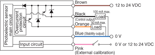
* The FS-M1P does not have a pink cable (for external calibration).
When the stability output is not used, cut the orange cable at the base, or connect this cable to
the 0 V terminal of the power supply.
External calibration input circuit
NPN
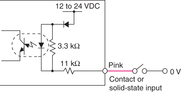
When the external calibration input is not used, cut the pink cable at the root, or connect this cable to the positive terminal of the power supply.
PNP
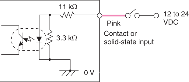
When the external calibration input is not used, cut the pink cable at the root, or connect this cable to the positive terminal of the power supply.