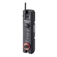
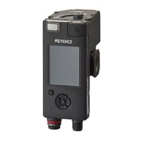
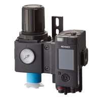
Air Efficiency Module
MP-F series
Specs Air Efficiency Module MP-F series
Air Efficiency Module
|
Model |
MP-FR10 |
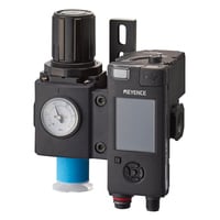
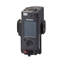
MP-FR10R |
MP-FR20 |
MP-FR20R |
MP-FR80 |
|||
|
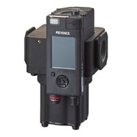
Image |
|
|
|
|
|
|||
|
Type |
Single model |
Standard model |
Single model |
Standard model |
Single model |
|||
|
Connection diameter |
Rc3/8 (10 A) |
Rc1/2 (15 A) |
Rc1 (25 A) |
|||||
|
Supported fluids |
Air, non-corrosive gases |
|||||||
|
Supported fluid temperatures |
–5 to +50°C |
|||||||
|
Operating pressure range |
0.2 to 1 MPa *1 |
|||||||
|
Pressure resistance |
1.5 MPa |
|||||||
|
Flow |
Detection principle |
Thermal method (mass flow) |
||||||
|
Rated flow range (normal) |
2.0 to 1000.0 L/min |
4 to 2000 L/min |
12 to 8000 L/min |
|||||
|
Zero cut flow rate |
2.0 L/min, 0.12 m3/h |
4 L/min, 0.2 m3/h |
12 L/min, 0.7 m3/h |
|||||
|
Measurement accuracy |
±(1.5% of RD + 0.5% of F.S.) *2 *3 |
|||||||
|
Repeatability |
±1.0% of F.S. (at averaging time of 1.0 s) |
|||||||
|
Display resolution |
0.1 L/min, 0.01 m3/h |
1 L/min, 0.1 m3/h |
||||||
|
Response time |
150 ms (63% response) *4 |
|||||||
|
Averaging time |
Select from OFF, 100 ms, 200 ms, 500 ms, 1.0 s, 3.0 s, 5.0 s, 10 s, 30 s |
|||||||
|
Pressure (digital value, gauge pressure) |
Rated pressure range |
0.000 to 1.000 MPa |
||||||
|
Measurement accuracy |
±2.0% of F.S. |
|||||||
|
Repeatability |
±0.2% of F.S. (at 50 ms response time) |
|||||||
|
Display resolution |
0.001 MPa |
|||||||
|
Response time |
Select from 10 ms/50 ms/100 ms/500 ms/1.0 s/5.0 s *4 |
|||||||
|
Humidity (dew point) |
Rated relative humidity range/dew point range |
15 to 100% RH (no condensation)/subject to relative humidity range *5 *6 |
||||||
|
Measurement accuracy |
±4°C *5 *6 |
|||||||
|
Display resolution |
5%RH/1°C *5 *6 |
|||||||
|
Temperature |
Measurement accuracy |
±2.0°C *7 |
||||||
|
Display resolution |
0.1°C *7 |
|||||||
|
Shutoff valve |
Response time |
Less than 1 s (closed > open) |
||||||
|
Leakage |
50 mL/min (N) or less |
|||||||
|
Filter regulator (standard model only) |
Pressure adjustment range |
─ |
0.15 to 0.90 MPa |
─ |
0.15 to 0.90 MPa |
─ |
||
|
Filtration rating |
5 μm |
5 μm |
||||||
|
Drain cup capacity |
60 cc |
100 cc |
||||||
|
Check valve |
Available |
|||||||
|
Display |
Colour LCD, status indicators |
|||||||
|
Data accumulation |
Accumulation period |
Accumulated data: approx. 2 years/Instantaneous data: approx. 2 weeks |
||||||
|
Data reading |
USB 2.0/Ethernet |
|||||||
|
Input/output |
Control output (Ch.1/2/3/4/5) |
NPN/PNP setting switchable, Open collector output: 30 VDC or less, N.O./N.C. setting switchable, max. 100 mA or less/Ch., Residual voltage: 2.5 V or less |
||||||
|
Analog output (Ch. 1/2) |
4-20 mA, Load resistance: 260 Ω or less *4 |
|||||||
|
External input (Ch. 2/3/6) |
Short circuit current: 1.5 mA or less; Input time: 20 ms or less |
|||||||
|
Protection circuit |
Protection against reverse power connection, power supply surges, reverse connection of inputs/outputs, input/output short circuits, output overcurrent |
|||||||
|
Power supply |
Power voltage |
24 VDC +25%/-20% (including ripple) Class 2 or LPS |
||||||
|
Current consumption |
1.2 A (300 ms) when the valve is open/closed, 100 mA *8 when the valve is not open/closed (when used alone, excluding load current) |
|||||||
|
Communication interface |
USB 2.0 |
|||||||
|
Network compatibility |
When using only this unit: IO-Link (Specification v1.1/COM3) *9 |
|||||||
|
Environmental resistance |
Enclosure rating |
IP67 (IEC 60529) *10 |
||||||
|
Ambient temperature |
−5 to +50°C (no freezing) *11 |
|||||||
|
Relative humidity |
35 to 85% RH (no condensation) |
|||||||
|
Vibration resistance |
10 to 500 Hz; Power spectral density: 0.204 G2/Hz; X, Y, and Z directions |
|||||||
|
Shock resistance |
300 m/s2; 10 times each for X, Y, and Z directions |
|||||||
|
Material |
Sensor: PET/PPS/PBT/POM/Aluminium/SPHC |
|||||||
|
Weight |
Approx. 550 g |
Approx. 1050 g (excluding drain cup) |
Approx. 1020 g |
Approx. 1900 g (excluding drain cup) |
Approx. 1920 g |
|||
|
*1 The shutoff valve is subject to flow characteristic deterioration when the primary side pressure is less than 0.2 MPa (for standard models, the adjustment pressure of the filter regulator is 0.2 MPa or less). |
||||||||
Air Efficiency Module
|
Model |
MP-FG10 |
MP-FG10R |
MP-FG20 |
MP-FG20R |
MP-FG80 |
|||
|
Image |
|
|
|
|
|
|||
|
Type |
Single model |
Standard model |
Single model |
Standard model |
Single model |
|||
|
Connection diameter |
G3/8 (10 A) |
G1/2 (15 A) |
G1 (25 A) |
|||||
|
Supported fluids |
Air, non-corrosive gases |
|||||||
|
Supported fluid temperatures |
–5 to +50°C |
|||||||
|
Operating pressure range |
0.2 to 1 MPa *1 |
|||||||
|
Pressure resistance |
1.5 MPa |
|||||||
|
Flow |
Detection principle |
Thermal method (mass flow) |
||||||
|
Rated flow range (normal) |
2.0 to 1000.0 L/min |
4 to 2000 L/min |
12 to 8000 L/min |
|||||
|
Zero cut flow rate |
2.0 L/min, 0.12 m3/h |
4 L/min, 0.2 m3/h |
12 L/min, 0.7 m3/h |
|||||
|
Measurement accuracy |
±(1.5% of RD + 0.5% of F.S.) *2 *3 |
|||||||
|
Repeatability |
±1.0% of F.S. (at averaging time of 1.0 s) |
|||||||
|
Display resolution |
0.1 L/min, 0.01 m3/h |
1 L/min, 0.1 m3/h |
||||||
|
Response time |
150 ms (63% response) *4 |
|||||||
|
Averaging time |
Select from OFF, 100 ms, 200 ms, 500 ms, 1.0 s, 3.0 s, 5.0 s, 10 s, 30 s |
|||||||
|
Pressure (digital value, gauge pressure) |
Rated pressure range |
0.000 to 1.000 MPa |
||||||
|
Measurement accuracy |
±2.0% of F.S. |
|||||||
|
Repeatability |
±0.2% of F.S. (at 50 ms response time) |
|||||||
|
Display resolution |
0.001 MPa |
|||||||
|
Response time |
Select from 10 ms/50 ms/100 ms/500 ms/1.0 s/5.0 s *4 |
|||||||
|
Humidity (dew point) |
Rated relative humidity range/dew point range |
15 to 100% RH (no condensation)/subject to relative humidity range *5 *6 |
||||||
|
Measurement accuracy |
±4°C *5 *6 |
|||||||
|
Display resolution |
5%RH/1°C *5 *6 |
|||||||
|
Temperature |
Measurement accuracy |
±2.0°C *7 |
||||||
|
Display resolution |
0.1°C *7 |
|||||||
|
Shutoff valve |
Response time |
Less than 1 s (closed > open) |
||||||
|
Leakage |
50 mL/min (N) or less |
|||||||
|
Filter regulator (standard model only) |
Pressure adjustment range |
─ |
0.15 to 0.90 MPa |
─ |
0.15 to 0.90 MPa |
─ |
||
|
Filtration rating |
5 μm |
5 μm |
||||||
|
Drain cup capacity |
60 cc |
100 cc |
||||||
|
Check valve |
Available |
|||||||
|
Display |
Colour LCD, status indicators |
|||||||
|
Data accumulation |
Accumulation period |
Accumulated data: approx. 2 years/Instantaneous data: approx. 2 weeks |
||||||
|
Data reading |
USB 2.0/Ethernet |
|||||||
|
Input/output |
Control output (Ch.1/2/3/4/5) |
NPN/PNP setting switchable, Open collector output: 30 VDC or less, N.O./N.C. setting switchable, max. 100 mA or less/Ch., Residual voltage: 2.5 V or less |
||||||
|
Analog output (Ch. 1/2) |
4-20 mA, Load resistance: 260 Ω or less *4 |
|||||||
|
External input (Ch. 2/3/6) |
Short circuit current: 1.5 mA or less; Input time: 20 ms or less |
|||||||
|
Protection circuit |
Protection against reverse power connection, power supply surges, reverse connection of inputs/outputs, input/output short circuits, output overcurrent |
|||||||
|
Power supply |
Power voltage |
24 VDC +25%/-20% (including ripple) Class 2 or LPS |
||||||
|
Current consumption |
1.2 A (300 ms) when the valve is open/closed, 100 mA *8 when the valve is not open/closed (when used alone, excluding load current) |
|||||||
|
Communication interface |
USB 2.0 |
|||||||
|
Network compatibility |
When using only this unit: IO-Link (Specification v1.1/COM3) *9 |
|||||||
|
Environmental resistance |
Enclosure rating |
IP67 (IEC 60529) *10 |
||||||
|
Ambient temperature |
−5 to +50°C (no freezing) *11 |
|||||||
|
Relative humidity |
35 to 85% RH (no condensation) |
|||||||
|
Vibration resistance |
10 to 500 Hz; Power spectral density: 0.204 G2/Hz; X, Y, and Z directions |
|||||||
|
Shock resistance |
300 m/s2; 10 times each for X, Y, and Z directions |
|||||||
|
Material |
Sensor: PET/PPS/PBT/POM/Aluminium/SPHC |
|||||||
|
Weight |
Approx. 550 g |
Approx. 1050 g (excluding drain cup) |
Approx. 1020 g |
Approx. 1900 g (excluding drain cup) |
Approx. 1920 g |
|||
|
*1 The shutoff valve is subject to flow characteristic deterioration when the primary side pressure is less than 0.2 MPa (for standard models, the adjustment pressure of the filter regulator is 0.2 MPa or less). |
||||||||
Air Efficiency Module
|
Model |
MP-FN10 |
MP-FN10R |
MP-FN20 |
MP-FN20R |
MP-FN80 |
|||
|
Image |
|
|
|
|
|
|||
|
Type |
Single model |
Standard model |
Single model |
Standard model |
Single model |
|||
|
Connection diameter |
NPT3/8 (10 A) |
NPT1/2 (15 A) |
NPT1 (25 A) |
|||||
|
Supported fluids |
Air, non-corrosive gases |
|||||||
|
Supported fluid temperatures |
–5 to +50°C |
|||||||
|
Operating pressure range |
0.2 to 1 MPa *1 |
|||||||
|
Pressure resistance |
1.5 MPa |
|||||||
|
Flow |
Detection principle |
Thermal method (mass flow) |
||||||
|
Rated flow range (normal) |
2.0 to 1000.0 L/min |
4 to 2000 L/min |
12 to 8000 L/min |
|||||
|
Zero cut flow rate |
2.0 L/min, 0.12 m3/h |
4 L/min, 0.2 m3/h |
12 L/min, 0.7 m3/h |
|||||
|
Measurement accuracy |
±(1.5% of RD + 0.5% of F.S.) *2 *3 |
|||||||
|
Repeatability |
±1.0% of F.S. (at averaging time of 1.0 s) |
|||||||
|
Display resolution |
0.1 L/min, 0.01 m3/h |
1 L/min, 0.1 m3/h |
||||||
|
Response time |
150 ms (63% response) *4 |
|||||||
|
Averaging time |
Select from OFF, 100 ms, 200 ms, 500 ms, 1.0 s, 3.0 s, 5.0 s, 10 s, 30 s |
|||||||
|
Pressure (digital value, gauge pressure) |
Rated pressure range |
0.000 to 1.000 MPa |
||||||
|
Measurement accuracy |
±2.0% of F.S. |
|||||||
|
Repeatability |
±0.2% of F.S. (at 50 ms response time) |
|||||||
|
Display resolution |
0.001 MPa |
|||||||
|
Response time |
Select from 10 ms/50 ms/100 ms/500 ms/1.0 s/5.0 s *4 |
|||||||
|
Humidity (dew point) |
Rated relative humidity range/dew point range |
15 to 100% RH (no condensation)/subject to relative humidity range *5 *6 |
||||||
|
Measurement accuracy |
±4°C *5 *6 |
|||||||
|
Display resolution |
5%RH/1°C *5 *6 |
|||||||
|
Temperature |
Measurement accuracy |
±2.0°C *7 |
||||||
|
Display resolution |
0.1°C *7 |
|||||||
|
Shutoff valve |
Response time |
Less than 1 s (closed > open) |
||||||
|
Leakage |
50 mL/min (N) or less |
|||||||
|
Filter regulator (standard model only) |
Pressure adjustment range |
─ |
0.15 to 0.90 MPa |
─ |
0.15 to 0.90 MPa |
─ |
||
|
Filtration rating |
5 μm |
5 μm |
||||||
|
Drain cup capacity |
60 cc |
100 cc |
||||||
|
Check valve |
Available |
|||||||
|
Display |
Colour LCD, status indicators |
|||||||
|
Data accumulation |
Accumulation period |
Accumulated data: approx. 2 years/Instantaneous data: approx. 2 weeks |
||||||
|
Data reading |
USB 2.0/Ethernet |
|||||||
|
Input/output |
Control output (Ch.1/2/3/4/5) |
NPN/PNP setting switchable, Open collector output: 30 VDC or less, N.O./N.C. setting switchable, max. 100 mA or less/Ch., Residual voltage: 2.5 V or less |
||||||
|
Analog output (Ch. 1/2) |
4-20 mA, Load resistance: 260 Ω or less *4 |
|||||||
|
External input (Ch. 2/3/6) |
Short circuit current: 1.5 mA or less; Input time: 20 ms or less |
|||||||
|
Protection circuit |
Protection against reverse power connection, power supply surges, reverse connection of inputs/outputs, input/output short circuits, output overcurrent |
|||||||
|
Power supply |
Power voltage |
24 VDC +25%/-20% (including ripple) Class 2 or LPS |
||||||
|
Current consumption |
1.2 A (300 ms) when the valve is open/closed, 100 mA *8 when the valve is not open/closed (when used alone, excluding load current) |
|||||||
|
Communication interface |
USB 2.0 |
|||||||
|
Network compatibility |
When using only this unit: IO-Link (Specification v1.1/COM3) *9 |
|||||||
|
Environmental resistance |
Enclosure rating |
IP67 (IEC 60529) *10 |
||||||
|
Ambient temperature |
−5 to +50°C (no freezing) *11 |
|||||||
|
Relative humidity |
35 to 85% RH (no condensation) |
|||||||
|
Vibration resistance |
10 to 500 Hz; Power spectral density: 0.204 G2/Hz; X, Y, and Z directions |
|||||||
|
Shock resistance |
300 m/s2; 10 times each for X, Y, and Z directions |
|||||||
|
Material |
Sensor: PET/PPS/PBT/POM/Aluminium/SPHC |
|||||||
|
Weight |
Approx. 550 g |
Approx. 1050 g (excluding drain cup) |
Approx. 1020 g |
Approx. 1900 g (excluding drain cup) |
Approx. 1920 g |
|||
|
*1 The shutoff valve is subject to flow characteristic deterioration when the primary side pressure is less than 0.2 MPa (for standard models, the adjustment pressure of the filter regulator is 0.2 MPa or less). |
||||||||
Energy Monitor
|
Model |
MP-FEA1 |
|||
|
Image |
|
|||
|
Measurement specifications |
Phase wire system |
1-phase 2-wire, 1-phase 3-wire, 3-phase 3-wire, 3-phase 4-wire (switchable) |
||
|
No. of measurement circuits |
1 circuit (maximum of 2 circuits in a 1-phase 2-wire configuration *1) |
|||
|
Input specifications |
Primary side rated current (In) |
Dedicated MP-FEC100 CT: 100 A, or general-purpose CT (secondary side rated input current 1 A) *2 |
||
|
Overcurrent withstand capability |
1.2 times the primary side rated current (can be continuous), 10 times the primary side rated current (1 sec or less) |
|||
|
Rated input voltage |
1-phase 2-wire |
When using MP-FEC100/MP-FEC250/MP-FEC600 or general-purpose CT: 100 VAC to 277 VAC (L-N) |
||
|
1-phase 3-wire |
When using MP-FEC100/MP-FEC250/MP-FEC600 or general-purpose CT: 100 VAC to 240 VAC (L-N), 200 VAC to 480 VAC (L-L) |
|||
|
3-phase 3-wire |
When using MP-FEC100/MP-FEC250/MP-FEC600 or general-purpose CT: 173 VAC to 480 VAC (L-L) |
|||
|
3-phase 4-wire |
When using MP-FEC100/MP-FEC250/MP-FEC600 or general-purpose CT: 100 to 277 VAC (L-N), 173 to 480 VAC (L-L) |
|||
|
Maximum allowable earth voltage |
When using MP-FEC100/MP-FEC250/MP-FEC600 or general-purpose CT: 480 VAC to earth |
|||
|
Input voltage fluctuation range constant |
-15% to +15% of rated input voltage |
|||
|
Rated input frequency |
50/60 Hz |
|||
|
Displayable range |
Voltage |
Display resolution: 0.1 [V] |
||
|
Current |
Display resolution: 0.001 [A] |
|||
|
Active power/Reactive power/Apparent power |
-8942.400 to +8942.400 [kW/kvar/kVA], Display resolution: 0.001 [kW/kvar/kVA] |
|||
|
Active energy/Reactive energy/Apparent energy |
0.000 to 999999.999 [kWh/kvarh/kVAh], Display resolution: 0.001 [kWh/kvarh/kVAh] |
|||
|
Power factor (PF) |
-1.00 to 1.00, Display resolution: 0.01 |
|||
|
Frequency |
0.0 to 90.0 [Hz], Display resolution: 0.1 [Hz] |
|||
|
Measurement accuracy |
Voltage |
±0.5% of RD (within rated input voltage) *3 |
||
|
Current |
・When using MP-FEC100/MP-FEC250/MP-FEC600 or general-purpose CT: ±0.5% of RD (5% ≤ In ≤ 120%), ±1.0% of RD (1% ≤ In < 5%) *2 *3 |
|||
|
Active energy |
・When using MP-FEC100/MP-FEC250/MP-FEC600 or general-purpose CT: Complies with IEC62053-22 §7.9 table 3 class 0.5 *2 *3 |
|||
|
Reactive energy |
・When using MP-FEC100/MP-FEC250/MP-FEC600 or general-purpose CT: Complies with IEC62053-23 §7.9 table 3 class 2 *2 *3 |
|||
|
Apparent energy |
・When using MP-FEC100/MP-FEC250/MP-FEC600 or general-purpose CT: ±0.5% of RD (5% ≤ In ≤ 120%), ±1.0% of RD (1% ≤ In < 5%) *2 *3 *4 |
|||
|
Effects of ambient temperature |
±0.03%/K *3 *5 |
|||
|
Effects of harmonics |
±0.5% of RD *3 *6 |
|||
|
Power factor (PF) |
±0.01 *3 |
|||
|
Frequency |
±0.1 [Hz] *3 |
|||
|
Current consumption |
36 mA |
|||
|
Withstand voltage |
Between all terminals and case: 2500 VAC for 1 minute |
|||
|
Insulation resistance |
Between all terminals and case: at least 20 MΩ min (500 VDC), Between voltage measurement terminals |
|||
|
Environmental resistance |
Ambient temperature |
-5 to +55°C (no freezing) |
||
|
Relative humidity |
35 to 85% RH (no condensation) |
|||
|
Measurement category |
ll |
|||
|
Usage altitude |
2500 m or less |
|||
|
Pollution degree |
2 |
|||
|
Installation method |
DIN rail |
|||
|
Vibration resistance |
10 to 500 Hz; Power Spectral Density: 0.033 G2/Hz for X, Y and Z directions |
|||
|
Shock resistance |
150 m/s2, 2 times each for X, Y, and Z directions |
|||
|
Material |
Polycarbonate |
|||
|
Weight |
Approx. 110 g |
|||
|
*1 When measuring two circuits, use the same voltage and phase for the two circuits to be measured. Also, use CT of the same model. |
||||
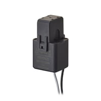
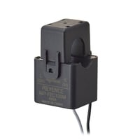
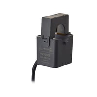
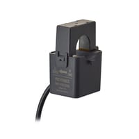
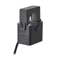
CT (external current sensor)
|
Model |
MP-FEC50M |
MP-FEC100M |
MP-FEC100 |
MP-FEC250 |
MP-FEC600 |
|||
|
Image |
|
|
|
|
|
|||
|
Primary side rated current (In) |
50 A |
100 A |
250 A |
600 A |
||||
|
Overcurrent withstand capability |
1.2 times the primary side rated current (can be continuous) |
|||||||
|
Maximum wire diameter that can be installed |
ø10 |
ø16 |
ø24 |
ø35 |
||||
|
Installation method |
Clamp type (split core) |
|||||||
|
Ratio error to current load |
±0.5% of RD (20% ≤ In ≤ 100%) |
±2.0% of RD (20% ≤ In ≤ 100%) |
±1.0% of RD (20% ≤ In ≤ 100%) |
|||||
|
Phase difference for current load |
±90’ (20% In) ±90’ (100% In) |
±240’ (20% In) ±180’ (100% In) |
±60’ (20% In) ±60’ (100% In) |
|||||
|
Withstand voltage |
2300 VAC for 1 minute (between core and output line) |
|||||||
|
Insulation resistance |
500 VDC/100 MΩ or more (between core and output line) |
|||||||
|
Protection elements |
Internal clamping element |
|||||||
|
Environmental resistance |
Ambient temperature |
-10 to +55°C (no freezing) |
||||||
|
Relative humidity |
35 to 85% RH (no condensation) |
|||||||
|
Material |
Nylon |
|||||||
|
Weight |
Approx. 140 g (with cable) |
Approx. 170 g (with cable) |
Approx. 300 g (with cable) |
Approx. 315 g (with cable) |
Approx. 450 g (with cable) |
|||
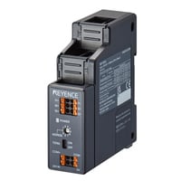
Ethernet Module
|
Model |
MP-FEN1 |
|||
|
Image |
|
|||
|
Ethernet specifications |
Compliant standards |
IEEE802.3u (100BASE-TX) |
||
|
Transmission rate |
100 Mbps (100BASE-TX) |
|||
|
Transmission medium |
Category 5 or better STP (Shielded Twisted Pair) |
|||
|
Connector type |
M12, 4-pin, female, D-code |
|||
|
Maximum cable length |
100 m (between nodes) |
|||
|
Compatible network |
EtherNet/IP®, PROFINET, Modbus/TCP, MC Protocol/SLMP |
|||
|
Connected model/No. of units |
MP-F main unit: 1 unit |
|||
|
EtherNet/IP® |
Supported functions |
Cyclic communication (Implicit messaging) |
||
|
No. of connections |
16 |
|||
|
Supported connections |
Input Only, Exclusive Owner |
|||
|
RPI (communication cycle) |
4 to 10,000 ms |
|||
|
PROFINET |
Compatible network |
PROFINET IO communication |
||
|
Supported functions |
Cyclic communication (Data I/O communication) |
|||
|
Conformance class |
Conforms to Conformance Class B |
|||
|
Conformance test version |
Conforms to Ver. 2.42 |
|||
|
Applicable protocol |
LLDP, SNMP, DCP |
|||
|
Net loading |
Class 2 |
|||
|
Cyclic update time |
4 ms to 2048 ms |
|||
|
Modbus/TCP |
Communication method |
TCP/IP |
||
|
Supported configurations |
Server |
|||
|
Maximum no. of simultaneously connected clients |
4 |
|||
|
MC Protocol/SLMP |
Communication method |
TCP/IP, UDP/IP |
||
|
Maximum connections |
4 |
|||
|
Supported frames |
QnA-compatible 3E frame, 4E frame |
|||
|
Data format |
Binary/ASCII |
|||
|
Power supply specifications |
Connector type |
M12, 4-pin, A-Code, male, cable length: 50 cm |
||
|
Power voltage |
24 VDC +25%/-20% (including ripple) Class2 or LPS |
|||
|
Current consumption |
40 mA |
|||
|
Environmental resistance |
Enclosure rating |
IP67 (IEC60529) |
||
|
Ambient temperature |
−20 to 60°C (no freezing) |
|||
|
Relative humidity |
35 to 85% RH (no condensation) |
|||
|
Vibration resistance |
10 to 500 Hz; Power spectral density: 0.816 G2/Hz; X, Y and Z directions |
|||
|
Shock resistance |
100 m/s2; 1000 times each for X, Y, and Z directions |
|||
|
Material |
Housing: PBT/PAR |
|||
|
Weight |
Approx. 150 g |
|||